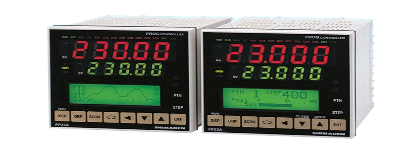
Programmable Controller : FP23A
A programmable controller capable of high resolution 1/1000℃ display which is suitable for high precision process.
Can select 2-input specification or servo output specification.Can be set at program pattern number: maximum 20 patterns; program step number: maximum 400 steps.3-point event output is a standard feature.
4-point external control input is a standard feature.
3-point (Darlington), 2-point (open collector) external control output is a standard feature.
A dustproof and drip-proof structure suitable for IP66.
Feature:
- 2-channel controller (Basic type: 1-channel controller)
- Independent 2-loop / 2-input operation control
- High accuracy ± (0.1% FS + 1 digit)
- High Sampling Cycle 0.1 sec.
- High resolution 1/ 1000 °C display achieved
- *Only for R.T.D. input (scale: 0.000~30.000 °C)
- Programmable Max. 400steps (400 steps x 1 pattern to 20 steps x 20 patterns)
- Auto-Tuning PID / Expert PID
- Max. 10 Zone PID control available
- Independent Universal-Input
- User Friendly Operation (Menu Driven: 4 Lines LCD Display)
- Easy Setting & Maintenance via Infrared COM port on the front panel
- Interface RS-232C/RS-485 (MODBUS / Shimaden)
- The front dust/splash-proof IP66
- Universal Power Supply (100~240V AC ±10%)
- Sensor power supply option (24Vdc 25mA)
1-input Specification
•1-output control
Ordering Information
|
ITEM |
CODE |
Specifications |
||||||||||||
|
SERIES |
FP23A- |
|
96 × 96 DIN size, high-performance programmable controller |
|||||||||||
|
BASIC FUNCTIONS |
SS |
|
Universal-input, 1-input/1-output control, 3 event outputs |
|||||||||||
|
CONTROL OUTPUT 1 |
Y |
|
Contact 1c, contact rating: 240V AC 2.5A/resistive load, 1A/inductive load |
|||||||||||
|
I |
|
Current 4 to 20mA DC, Load resistance: max. 600 Ω |
||||||||||||
|
P |
|
SSR drive voltage output 12V±1.5V DC, Load current: max. 30mA |
||||||||||||
|
V |
|
Voltage 0 to 10V DC, Load current: max. 2mA |
||||||||||||
|
CONTROL OUTPUT 2 |
N- |
|
None |
|||||||||||
|
HEATER BREAK ALARM (FOR SINGLE-PHASE) |
00 |
|
None |
|||||||||||
|
31 |
|
Heater break alarm* (heater current 30A with CT) |
* Selectable only when Control Output 1 is Y or P |
|||||||||||
|
32 |
|
Heater break alarm* (heater current 50A with CT) |
||||||||||||
|
ANALOG OUTPUT 1 |
0 |
|
None |
|||||||||||
|
3 |
|
0 to 10mV DC, Output resistance: 10Ω |
||||||||||||
|
4 |
|
4 to 20mA DC, Load resistance: max. 300Ω |
||||||||||||
|
6 |
|
0 to 10V DC, Load current: max. 2mA |
||||||||||||
|
ANALOG OUTPUT 2/ SENSOR POWER SUPPLY |
0 |
|
None |
|||||||||||
|
3 |
|
0 to 10mV DC, Output resistance: 10Ω |
||||||||||||
|
4 |
|
4 to 20mA DC, Load resistance: max. 300 Ω |
||||||||||||
|
6 |
|
0 to 10V DC, Load current: max. 2mA |
||||||||||||
|
8 |
|
Sensor power supply 24V DC 25mA |
||||||||||||
|
EXTERNAL INPUT/ |
standard |
0 |
|
DI 4 points, DO 5 points (start pattern No. switching not available) |
||||||||||
|
OUTPUT CONTROL SIGNAL (DI/DO) *1 |
1 |
|
DI 10 points, DO 9 points (start pattern No. switching available) |
|||||||||||
|
2 |
|
DI 10 points, DO 13 points (start pattern No. switching available) |
||||||||||||
|
COMMUNICATION FUNCTION |
0 |
|
None |
|||||||||||
|
5 |
|
RS-485 |
Shimaden standard protocol / MODBUS (RTU/ASCII) communication protocol |
|||||||||||
|
7 |
|
RS-232C |
||||||||||||
|
REMARKS |
0 |
Without |
||||||||||||
|
9 |
With |
|||||||||||||
*1 When switching the start pattern No. by DI, 10 points of DI (CODE 1 or 2) are required.
Optional Accessories
|
Name |
Model |
Description |
|
Infra-red Communication Adapter |
S5004 |
USB connector cable (2m), Setup Software (CD-ROM) |
|
Shunt Resistor |
QCS002 |
250Ω , external input resistance at current input |
|
Relay Unit |
AP2MC |
Converts open collector output to contact output. 2 circuits built-in |
1-input Specification
- 2-output control (Heating/cooling control)
Ordering Information
|
ITEM |
CODE |
Specifications |
||||||||||||
|
SERIES |
FP23A- |
|
96 × 96 DIN size, high-performance programmable controller |
|||||||||||
|
BASIC FUNCTIONS |
SD |
|
Universal-input, 1-input/2-output control, 3 event outputs |
|||||||||||
|
CONTROL OUTPUT 1 |
Y |
|
Contact 1c, contact rating: 240V AC 2.5A/resistive load, 1A/inductive load |
|||||||||||
|
I |
|
Current 4 to 20mA DC, Load resistance: max. 600Ω |
||||||||||||
|
P |
|
SSR drive voltage output 12V±1.5V DC, Load current: max. 30mA |
||||||||||||
|
V |
|
Voltage 0 to 10V DC, Load current: max. 2mA |
||||||||||||
|
CONTROL OUTPUT 2 |
Y- |
|
Contact 1c, contact rating: 240V AC 2.5A/resistive load, 1A/inductive load |
|||||||||||
|
I- |
|
Current 4 to 20mA DC, Load resistance: max. 600Ω |
||||||||||||
|
P- |
|
SSR drive voltage output 12V±1.5V DC, Load current: max. 30mA |
||||||||||||
|
V- |
|
Voltage 0 to 10V DC, Load current: max. 2mA |
||||||||||||
|
HEATER BREAK ALARM (FOR SINGLE-PHASE) *1 |
00 |
|
None |
|||||||||||
|
31 |
|
Heater break alarm* (heater current 30A with CT) |
* Selectable only when Control Output 1 or 2 is Y or P |
|||||||||||
|
32 |
|
Heater break alarm* (heater current 50A with CT) |
||||||||||||
|
ANALOG OUTPUT 1 |
0 |
|
None |
|||||||||||
|
3 |
|
0 to 10mV DC, Output resistance: 10 Ω |
||||||||||||
|
4 |
|
4 to 20mA DC, Load resistance: max. 300 Ω |
||||||||||||
|
6 |
|
0 to 10V DC, Load current: max. 2mA |
||||||||||||
|
ANALOG OUTPUT 2/ SENSOR POWER SUPPLY |
0 |
|
None |
|||||||||||
|
3 |
|
0 to 10mV DC, Output resistance: 10Ω |
||||||||||||
|
4 |
|
4 to 20mA DC, Load resistance: max. 300Ω |
||||||||||||
|
6 |
|
0 to 10V DC, Load current: max. 2mA |
||||||||||||
|
8 |
|
Sensor power supply 24V DC 25mA |
||||||||||||
|
EXTERNAL INPUT |
standard |
0 |
|
DI 4 points, DO 5 points (start pattern No. switching not available) |
||||||||||
|
/OUTPUT CONTROL SIGNAL (DI/DO) *2 |
1 |
|
DI 10 points, DO 9 points (start pattern No. switching available) |
|||||||||||
|
2 |
|
DI 10 points, DO 13 points (start pattern No. switching available) |
||||||||||||
|
COMMUNICATION FUNCTION |
0 |
|
None |
|||||||||||
|
5 |
|
RS-485 |
Shimaden standard protocol / MODBUS (RTU/ASCII) communication protocol |
|||||||||||
|
7 |
|
RS-232C |
||||||||||||
|
REMARKS |
0 |
Without |
||||||||||||
|
9 |
With |
|||||||||||||
*1 In a 2-output specification, the heater break alarm is used by either of Control Output 1 or 2.
*2 When switching the SV No. by DI, 10 points of DI (CODE 1 or 2) are required.
Optional Accessories
|
Name |
Model |
Description |
|
Infra-red Communication Adapter |
S5004 |
USB connector cable (2m), Setup Software (CD-ROM) |
|
Shunt Resistor |
QCS002 |
250Ω , external input resistance at current input |
|
Relay Unit |
AP2MC |
Converts open collector output to contact output. 2 circuits built-in |
2-input Specification
- 2-input/2-output control (independent 2-loop control)
- 2-input operation/1-output control (1-loop control by max. value, min. value, average value, deviation value operation)
- 2-input operation/2-output control (1-loop heating/cooling control by max. value, min. value, average value, deviation value operation)
Ordering Information
|
ITEM |
CODE |
Specifications |
|||||||||||
|
SERIES |
FP23A- |
|
96 × 96 DIN size, high-performance digital controller |
||||||||||
|
BASIC FUNCTIONS *1 |
DL |
|
Universal-input, independent 2-loop control, 3 event outputs |
||||||||||
|
DS |
|
Universal-input, 2-input operation/1-output control, 3 event outputs *2 |
|||||||||||
|
DD |
|
Universal-input, 2-input operation/2-output control, 3 event outputs |
|||||||||||
|
CONTROL OUTPUT 1 *2 |
Y |
|
Contact 1c, contact rating: 240V AC 2.5A/resistive load, 1A/inductive load |
||||||||||
|
I |
|
Current 4 to 20mA DC, Load resistance: max. 600 Ω |
|||||||||||
|
P |
|
SSR drive voltage output 12V±1.5V DC, Load current: max. 30mA |
|||||||||||
|
V |
|
Voltage 0 to 10V DC, Load current: max. 2mA |
|||||||||||
|
CONTROL OUTPUT 2 |
Y- |
|
Contact 1c, contact rating: 240V AC 2.5A/resistive load, 1A/inductive load |
||||||||||
|
I- |
|
Current 4 to 20mA DC, Load resistance: max. 600Ω |
|||||||||||
|
P- |
|
SSR drive voltage 12V±1.5V DC, Load current: max. 30mA |
|||||||||||
|
V- |
|
Voltage 0 to 10V DC, Load current: max. 2mA |
|||||||||||
|
HEATER BREAK ALARM (FOR SINGLE-PHASE) *3 |
00 |
|
None |
||||||||||
|
31 |
|
Heater break alarm (heater current 30A with CT) |
Selectable only when Control Output 1 or 2 is Y or P |
||||||||||
|
32 |
|
Heater break alarm (heater current 50A with CT) |
|||||||||||
|
ANALOG OUTPUT 1 |
0 |
|
None |
||||||||||
|
3 |
|
0 to 10mV DC, Output resistance: 10Ω |
|||||||||||
|
4 |
|
4 to 20mA DC, Load resistance: max. 300 Ω |
|||||||||||
|
6 |
|
0 to 10V DC, Load current: max. 2mA |
|||||||||||
|
ANALOG OUTPUT 2/ SENSOR POWER SUPPLY |
0 |
|
None |
||||||||||
|
3 |
|
0 to 10mV DC, Output resistance: 10Ω |
|||||||||||
|
4 |
|
4 to 20mA DC, Load resistance: max. 300 Ω |
|||||||||||
|
6 |
|
0 to 10V DC, Load current: max. 2mA |
|||||||||||
|
8 |
|
Sensor power supply 24V DC 25mA |
|||||||||||
|
EXTERNAL INPUT/OUTPUT |
standard |
0 |
|
DI 4 points, DO 5 points (start pattern No. switching not available) |
|||||||||
|
CONTROL SIGNAL (DI/DO) *4 |
1 |
|
DI 10 points, DO 9 points (start pattern No. switching available) |
||||||||||
|
COMMUNICATION FUNCTION |
0 |
|
None |
||||||||||
|
5 |
|
RS-485 |
Shimaden standard protocol/MODBUS (RTU/ASCII) communication protocol |
||||||||||
|
7 |
|
RS-232C |
|||||||||||
|
REMARKS |
0 |
Without |
|||||||||||
|
9 |
With |
||||||||||||
*1 Independent 2-loop control, 2-input operation/1-output control and 2-input operation/2-output control are all supported in the 2-output specification. This controller is shipped with the function selected at BASIC FUNCTION set.
*2 In a 2-input operation/1-output control specification, output for control is output to Control Output 1. Select the same specification as Control Output 2 for Control Output 1.
*3 In a 2-output specification, the heater break alarm is used by either of Control Output 1 or 2.
*4 When switching the start pattern No. by DI, 10 points of DI (CODE 1) are required.
Optional Accessories
|
Name |
Model |
Description |
|
Infra-red Communication Adapter |
S5004 |
USB connector cable (2m), Setup Software (CD-ROM) |
|
Shunt Resistor |
QCS002 |
250Ω , external input resistance at current input |
|
Relay Unit |
AP2MC |
Converts open collector output to contact output. 2 circuits built-in |
Releted Products

Programmable Controller : FP93
Programmable controller with a bright, easy-to-see large LED display.
Can be set at program pattern number: maximum 4 patterns, program step number: maximum 40 steps.
Suitable for multi-input of thermocouple, RTD and voltage.
3-point event output is a standard feature.
4-point external control input is a standard feature.
A dustproof and drip-proof structure suitable for IP66.